Ports and Connections
This article covers the ports on the Behavior board, as well as how to connect the device to peripherals and external devices.
Ports
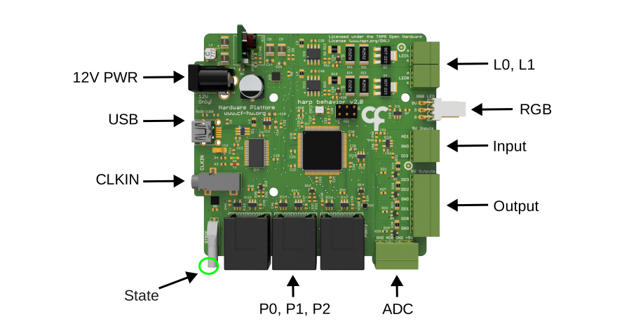
12V PWR (Barrel Jack) - This port powers the Behavior board and requires a 12 V power supply.
USB (Mini-B/USB-C) - This port connects the device to the control computer running Bonsai or the GUI. The connector type depends on the hardware version of the board.
CLKIN (Stereo Jack) - This Harp clock input accepts a clock output from any compatible Harp clock generator or synchronizer (e.g. Harp Timestamp Generator) for synchronization with other connected devices.
State - This status LED cycles on and off with a period of:
- 2 seconds when it's communicating with Bonsai
- 4 seconds when in standby
- 100 milliseconds when a catastrophic error occurs
P0, P1, P2 (RJ45) - These specialized peripheral ports interface directly with the Mice Poke peripheral for poke detection and reward delivery. Alternatively, use the Breakout extension board to interface with other peripherals and accessories. Port P2 additionally accepts the Rotary Encoder peripheral for rotation tracking.
ADC (Screw Terminal) - This connector carries the first analog input (AD0), a 5 V supply pin and two ground connections.
Output (Screw Terminal) - These general-purpose 5 V digital outputs can be used to communicate with external devices. DO0/DO1 can generate camera triggers and DO2/DO3 can drive servo motors; all four support PWM.
Input (Screw Terminal) - This connector carries the second analog input (AD1), the digital input DI3 and one ground connection. This connector is only available on hardware v2.0 or later boards.
RGB (3-pin Flick Lock) - Connector for up to two WS2812-type individually addressable RGB LEDs, driven as a serial chain on a single data line. Colors are set with the RGB registers.
L0, L1 (Screw Terminal) - These connectors control two regular current-controlled LED outputs. Each terminal pair is marked A (anode, the LED's long leg) and K (cathode, the short leg). The drive current is configurable from 2 to 100 mA.
Connections
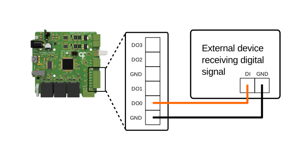
- Wire the external device's digital input to one of DO0–DO3 on the Output connector, and connect the external device's ground to any GND pin.
- Alternatively, use the Breakout board to unlock more digital outputs on the peripheral ports.
- Refer to the Control Digital Outputs article to switch the output in Bonsai.
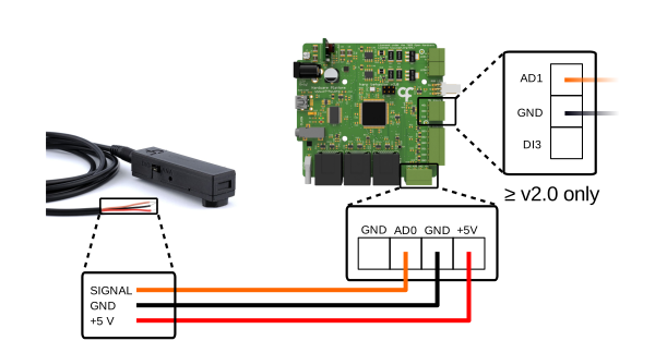
Before connecting the Photodiode peripheral, switch the jumper setting on the casing to either ANA for an analog reading or DIG for a digital output. Plug the stereo adapter cable into the stereo jack on the peripheral. The other end of the cable has three colored wires for the signal, 5 V supply and ground, as shown above.
For an analog reading:
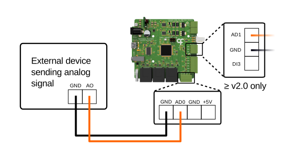
- Wire the signal wire to either AD0 on the ADC connector (shown above) or AD1 on the Input connector (hardware v2.0 or later).
- Wire the supply wire to any +5 V pin and the ground wire to any GND pin.
- Refer to the Acquire Analog Data article to read the light intensity as an analog reading in Bonsai.
Alternatively, for a digital output:
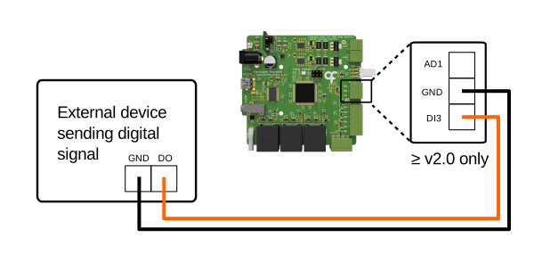
- Wire the signal wire to DI3 on the Input connector (hardware v2.0 or later) if you have access to it.
- Otherwise, use the Breakout board to unlock more digital inputs on the peripheral ports.
- Refer to the Read Digital Inputs article to read the light intensity as a digital input reading in Bonsai.
- Turn the adjustment screw to tune the light threshold for the low and high state of the digital output and monitor the response in Bonsai.
Note
Third-party photodiode modules that are powered with 5 V and output a 0 to 5 V signal can be wired the same way.
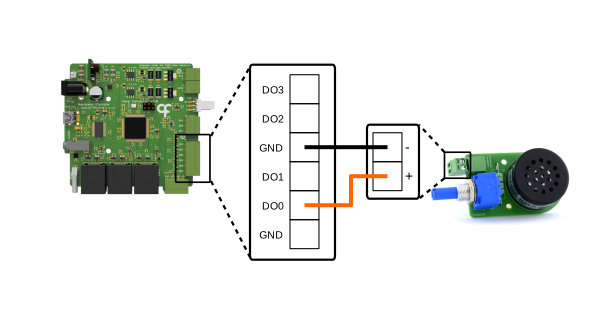
- Wire the Speaker peripheral to the Output connector: the + terminal to one of DO0–DO3 and the - terminal to any GND pin.
- Refer to the Generate PWM article to play tones in Bonsai.
Note
Third-party passive buzzers or speakers can be driven with PWM in the same way. Active buzzers generate a fixed tone, so switch them on and off like any other digital output (see Control Digital Outputs). Add a current-limiting series resistor (100 to 330 Ω) to avoid overloading the 5 V supply.
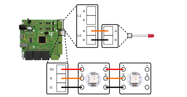
- Wire a standard LED to either the L0 or L1 terminal pair with the long leg (anode) to the A pin and the short leg (cathode) to K. No series resistor is needed as the drive current can be set in Bonsai.
- Connect a WS2812-type addressable RGB LED to the RGB connector with the signal wire going to S and the power and ground going to 5V and G.
- Up to two RGB LEDs can be driven. Connect the second one as a serial chain with the same wiring configuration.
- Refer to the Control LEDs article to configure and switch the LEDs in Bonsai.
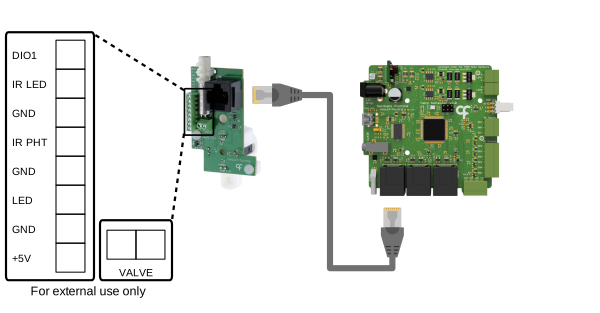
- Connect the Mice Poke peripheral to port P0, P1, or P2 with an RJ45 cable.
- If the peripheral comes with an integrated water valve, connect the valve's inlet to the liquid container with tubing (2.0 mm inner diameter FEP, or 2.1 mm PTFE).
- Refer to the Control Poke Peripheral article to configure and use the Mice Poke peripheral in Bonsai.
No further wiring is necessary. The screw terminal blocks are only needed for external use; they tap the same connections that are carried by the RJ45 connector.
Use them to control the peripheral from another device, log its signals, wire a different solenoid valve, or connect an extra sensor.
For wiring to the screw terminals:
- Share ground between the external device and any GND terminal.
- Use the +5V terminal to power the peripheral when it is not connected to the Behavior board, or to power external devices when it is. Never connect an external supply to +5V while the Behavior board is also connected.
- Wire external signals (5 V logic) to the labeled terminals:
- DIO1 - This line is not connected to any of the peripheral sensors and acts as an extra digital input (the functionality to toggle it to digital output has not been added yet). Use it to add an external sensor like a lever. The Behavior board reports the changes as port DIO events.
- IR LED, IR PHT - Connects to the infrared beam LED emitter, as well as the infrared photodetector. Use it to either control or mirror those signals.
- LED - Connected to the onboard cue LEDs. Use it to control the LED, mirror the signal, or add an extra LED (no series resistor is needed).
- To use your own solenoid valve for reward delivery, disconnect the integrated valve's leads from the VALVE terminal (if fitted) and wire a 12 V solenoid valve across the terminal pair. For standard coil-only solenoid valves, polarity does not matter.
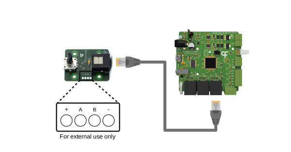
- Connect the Rotary Encoder peripheral to port P2 with an RJ45 cable. This is the only port with the quadrature counter functionality.
- Refer to the Track Rotary Encoder article to read the encoder in Bonsai.
No further wiring is necessary. The solder pads are only needed for external use; they share the same lines as the onboard rotary encoder. Use the solder pads to wire an external rotary encoder in place of the onboard one, tap the raw quadrature signals for logging, or to operate the peripheral from another device entirely.
For wiring to the solder pads:
- Share ground between the external device and the - pad.
- Use the + pad to power the external encoder when the Behavior board is connected, or to power the peripheral when it is not. Never connect an external supply to + while the Behavior board is also connected.
- Wire an external encoder's quadrature signals (5 V logic) to the A and B pads:
- Do not turn the onboard encoder while an external one is wired, as both share the same lines. Alternatively, disconnect the onboard rotary encoder.
- To log the raw quadrature signals from the onboard encoder instead, connect A and B to digital inputs.
An external rotary encoder can also be connected using the Breakout board, refer to the Breakout tab for more information.
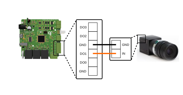
- Locate the GPIO (general purpose input/output) connector on your camera. Refer to the camera manual for the connector pinout as it varies widely between camera models and manufacturers.
- Check that the camera is compatible with the 5 V trigger signal from the Behavior board. For cameras with lower-voltage trigger inputs (e.g. 1.8 V or 3.3 V logic), add a level shifter between the output and the camera.
- Configure the external trigger in the camera vendor's software to use the rising edge of the trigger. Avoid modes that use the trigger pulse width to control exposure as the pulse width is fixed at half the trigger period.
- Wire the camera's external trigger input to DO0 or DO1 on the Output connector. These are the only ports that support the camera trigger functionality.
- Connect the camera's trigger ground to any GND pin.
- Refer to the Trigger Cameras article to configure and start the trigger in Bonsai.
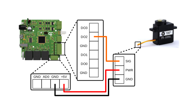
- Connect the servo signal wire to DO2 or DO3 on the Output connector. These are the only ports that support the servo functionality.
- Connect the servo power wire to the +5V pin on the ADC connector. For servos that draw more than 200 mA, or that require a supply voltage other than 5 V, power the servo from an external supply matching its rating instead. Never connect the external supply to the board's 5 V pin; it must power the servo only.
- Alternatively, use the Breakout board to unlock more power pins on the peripheral ports.
- Connect the servo ground wire to a GND pin. For servos requiring an external power supply, connect the external supply's ground to a GND pin.
- Refer to the Drive Servos article to move the servo in Bonsai.
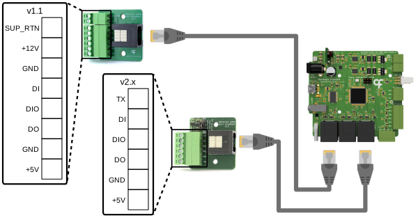
Both versions of the Breakout board are shown above. Follow the instructions for the version you have, some of the functionality is only available for a specific version.
For digital input and output connections (both):
- Connect the Breakout board to port P0, P1, or P2 with an RJ45 cable.
- Wire the signal wire from external devices to the DI, DIO, and DO screw terminals.
- Wire the +5V pin and GND pins to provide power and ground.
- Refer to the Read Digital Inputs and Control Digital Outputs articles to use these lines in Bonsai.
For connecting an external rotary encoder (both):
- Connect the Breakout board to port P2 with an RJ45 cable. The quadrature counter is only available on this port.
- Wire the encoder's A channel to the DI terminal and its B channel to the DIO terminal. Both channels must be 5 V logic.
- Wire the encoder's supply to the +5V terminal and its ground to a GND terminal. For encoders that require a different supply voltage, power the encoder from an external supply instead and share only its ground with a GND terminal.
- Leave any index (Z) output of the encoder unconnected as the Behavior board does not support it.
- Refer to the Track Rotary Encoder article to read the encoder in Bonsai. If the count runs in the opposite direction to the rotation, swap the A and B wires.
For valve control (v1.1 only):
- Connect the Breakout board to port P0, P1, or P2 with an RJ45 cable.
- Wire a 12 V solenoid valve between the +12V and SUP_RTN terminals.
- Refer to Deliver Rewards on Poke to pulse the valve line in Bonsai.
For streaming the serial timestamp (v2.x only):
- Connect the board to P2, the timestamp stream can only be transmitted on this port.
- Wire the TX terminal to the receiving device's RX input or to a logged digital input and a GND terminal to its ground.
- Set the board's logic-level jumper to match the receiver's operating voltage level (3.3 V or 5 V).
- Refer to the Stream Timestamps section to enable the stream in Bonsai.
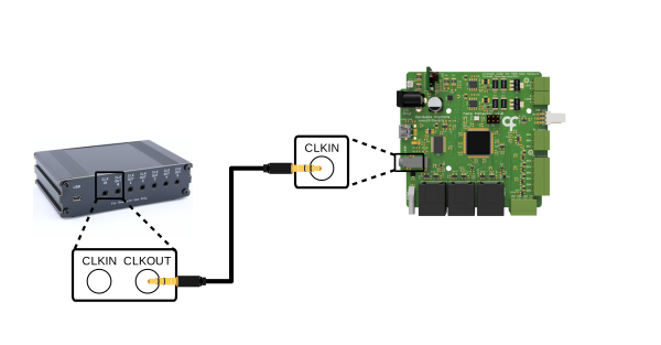
- Connect a clock output of a Harp clock generator (e.g. the Harp Timestamp Generator) to the CLKIN jack with a stereo plug cable.
- The Behavior board adopts the generator's clock automatically. To verify the connection, check that the STATE LEDs of the connected boards blink simultaneously.
- Refer to the Harp synchronization clock documentation for how devices synchronize.
Last updated with:
Hardware v2.1
Firmware v3.3
Bonsai Package v0.2